
CNC Machining Center X/Y Axis Drifting (Z Axis Correct) – Step-by-Step Troubleshooting Guide
Views :
0
Update time : 2026-07-31 17:25:06
1. Introduction: Common Fault Phenomenon
Many CNC machining centers experience consistent dimensional offset or random drifting on the X and Y axes, while the Z axis remains perfectly stable and accurate. This issue is extremely common in vertical machining centers and causes inconsistent part sizes, rework, and unstable mass production.
Since the Z axis works correctly, we can eliminate general faults such as main power failure, system board damage, overall grounding problems, and total servo system failure. The error is isolated to X/Y axis mechanical transmission, signal wiring, zero return system, or axis-specific parameters.
2. Two Main Types of X/Y Axis Drift
2.1 Random Drift (Unstable Offset Value)
The dimension error changes randomly in every cycle. Parts are sometimes larger, sometimes smaller.
Main causes: coupling slippage, mechanical backlash, loose wiring, encoder signal interference, unstable servo load.
2.2 Regular Directional Drift (Fixed Offset)
The X/Y axes always shift in the same direction with nearly the same error value.
Main causes: lost CNC parameters, zero-point drift, failed screw compensation, coordinate system offset, mechanical deformation under cutting force.
3. Step-by-Step Troubleshooting (From Simple to Complex)
Step 1: Confirm the Drift Occurrence Condition
Observe and record the fault scenario:
- Offset appears immediately after power-on and zero return → Faulty zero switch, loose dog block, unstable machine origin.
- Gradual drift after running for some time → Servo heating, internal friction, pulse loss, wiring instability.
- Dimension recovers after restarting the machine → Electromagnetic interference or temporary system signal error.
Step 2: Rule Out Software and Coordinate Errors
Many X/Y offset problems are caused by system settings instead of mechanical failure.
- Check whether G54–G59 workpiece coordinates are automatically changed by macro programs or manual operation.
- Confirm that abnormal tool radius compensation is not superimposed on X/Y movements.
- Run a simple test: Repeat
G90 G54 X0 Y0multiple times. If the physical position does not match the displayed coordinate, positioning failure is confirmed.
Judgment method:
If the screen coordinate is correct but the actual workpiece position drifts, the problem is mechanical slippage.
If both screen value and physical position drift, the problem is signal or parameter loss.
Step 3: Inspect Zero Return System (High-Frequency Fault)
Most incremental encoder machines rely on mechanical zero return. If the X/Y zero switch or dog block is loose, the origin will be different after each startup, causing continuous size deviation.
Quick test: Move axes manually and run machining without zero return. If the drift disappears, the zero return system is faulty.
Step 4: Check CNC Battery and Axis Parameters
A low CNC mainboard battery is one of the most hidden causes. It does not crash the whole system but causes partial loss of X/Y axis parameters, including screw compensation, backlash data, and origin parameters.
- Replace the battery if voltage is lower than 2.6V.
- Verify X/Y electronic gear ratio, position gain, speed gain, and backlash compensation parameters.
Step 5: Check Encoder Cables and Interference
X/Y axes are closer to the cutting area. Their encoder cables are easily corroded by cutting fluid or loosened by vibration, causing pulse loss.
- Power off and re-plug X/Y encoder connectors to eliminate poor contact.
- Check whether spindle and inverter cables interfere with encoder signal lines.
- Use fully shielded cables and ensure standard grounding if interference occurs when the spindle runs.
Step 6: Inspect Servo Motor Coupling (Most Common Cause)
In over 60% of X/Y drifting cases, the root cause is a worn or loose motor coupling.
The servo motor runs normally, but the screw slips slightly, resulting in inconsistent positioning. This fault does not trigger any servo alarm.
Inspection method: Open the axis guard and observe synchronous rotation of the motor shaft and screw shaft during reciprocating movement.
If asynchronous rotation is observed, replace the coupling immediately.
Step 7: Detect Mechanical Backlash and Axial Play
Use a dial indicator to test X/Y axis play:
- Normal play: ≤0.005 mm
- Abnormal play: >0.02 mm (causes obvious offset after direction reversal)
Check guide gib clearance and worktable locking screws. Loose gibs cause offset during heavy cutting.
Step 8: Repeat Positioning Accuracy Test
Run a simple positioning program repeatedly to verify stability:
G90 X0
G04 X0.5
G90 X100
G04 X0.5
Test 20 cycles. Large repeated errors indicate mechanical wear or insufficient servo rigidity.
4. Fault Phenomenon & Cause Matching Table
- Gradual drift during running, recover after restart → Signal interference, servo overheating, pulse loss
- Offset only occurs during cutting → Loose gibs, poor mechanical rigidity, coupling slip
- Different size after each power-on → Unstable zero return position
- Screen coordinate correct, actual size wrong → Pure mechanical slippage
- Random offset in idle running → Encoder connection failure
5. Standard Fixing Priority
- Check and replace low CNC battery
- Test machining with and without zero return
- Perform dial indicator positioning test
- Re-seat encoder connectors
- Inspect and replace X/Y couplings
- Measure axis backlash and guide clearance
- Verify all axis compensation parameters
- Eliminate electromagnetic interference
6. Common Maintenance Misunderstandings
- Do not blindly increase backlash compensation. Severe mechanical wear cannot be fixed by parameters alone.
- Low CNC battery only causes partial axis parameter loss, not full system failure.
- Slight coupling slippage produces no alarm code, making it hard to detect.
- X/Y axes suffer more cutting fluid corrosion than the Z axis.
7. Conclusion
When only the X and Y axes drift while the Z axis stays accurate, the problem is never a major system failure. It is almost always caused by zero return instability, parameter loss, signal interference, or mechanical transmission slippage.
Following this step-by-step method can quickly locate and solve 99% of X/Y offset faults on CNC machining centers, improving machining stability and product consistency.
Related News
Read More >>
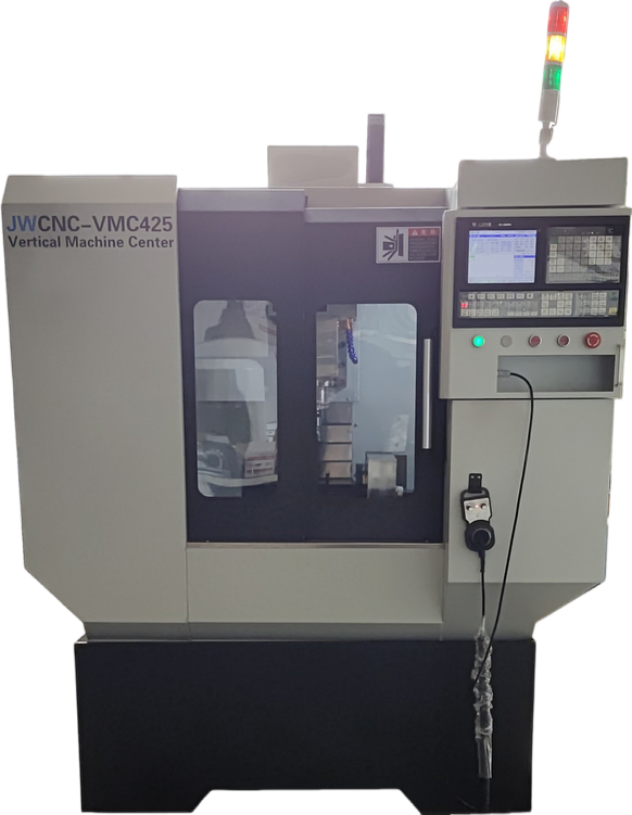 A Comprehensive Guide to Purchasing Small CNC Milling Machines in the U.S.
2026-08-22
Investing in a small CNC milling machine is a strategic decision for hobbyists, small businesses, and educational instit...
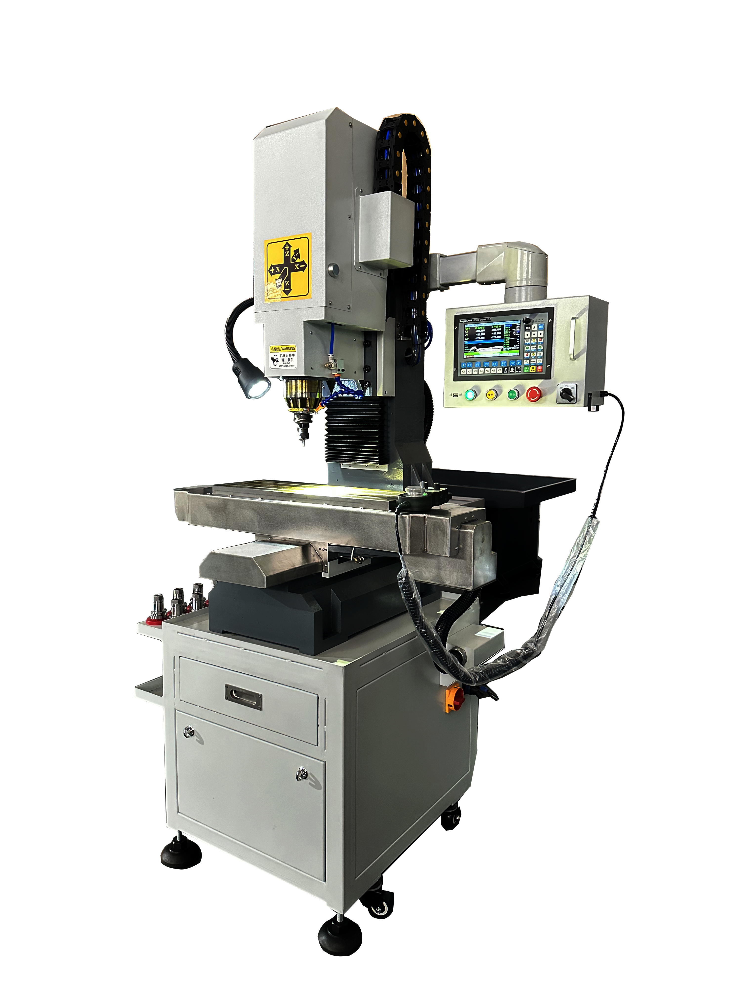 The Growing Role of Small CNC Milling Machines in Automotive and Motorcycle Parts Manufacturing: A Focus on Emerging Markets
2025-05-22
The global automotive and motorcycle parts industry is increasingly reliant on precision manufacturing technologies, wit...
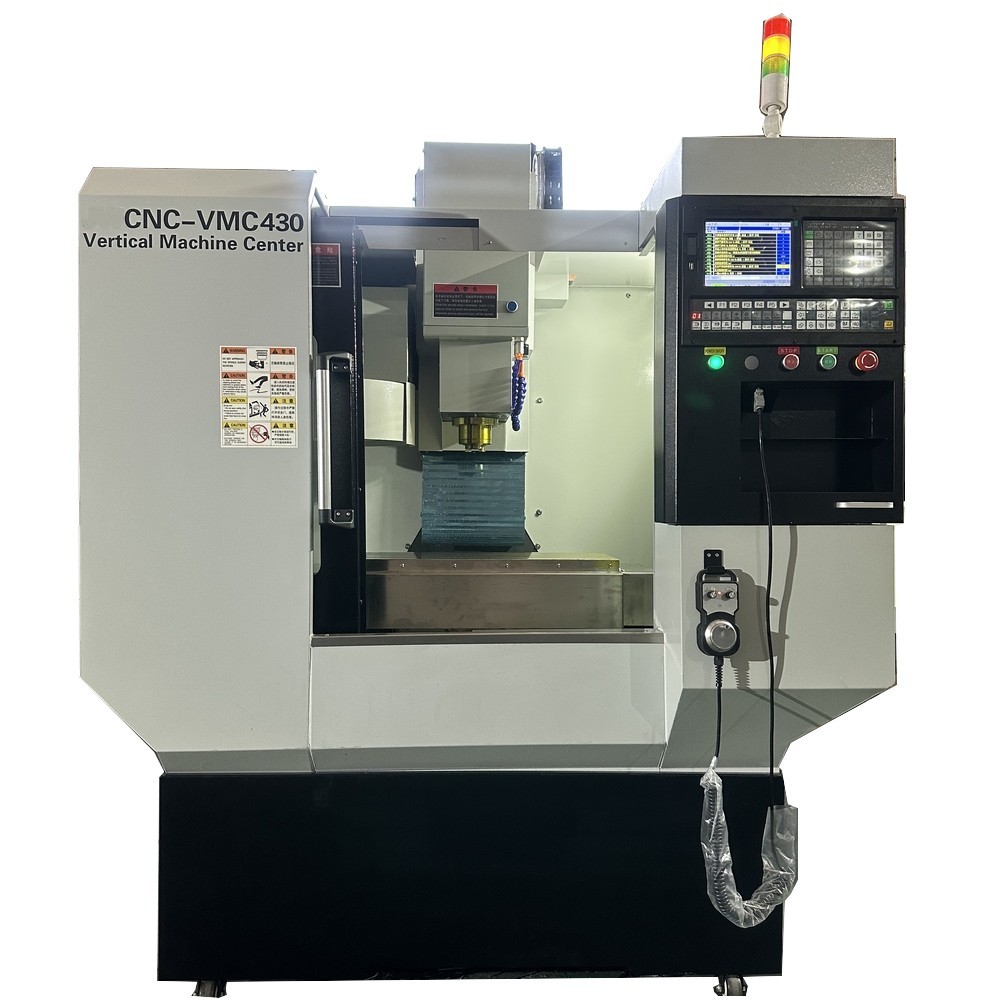 VMC430 Small CNC Milling Machine Tool Setting Operation Skills
2026-08-22
Complete Tool Setting Operation Steps for VMC430 CNC Milling Machine
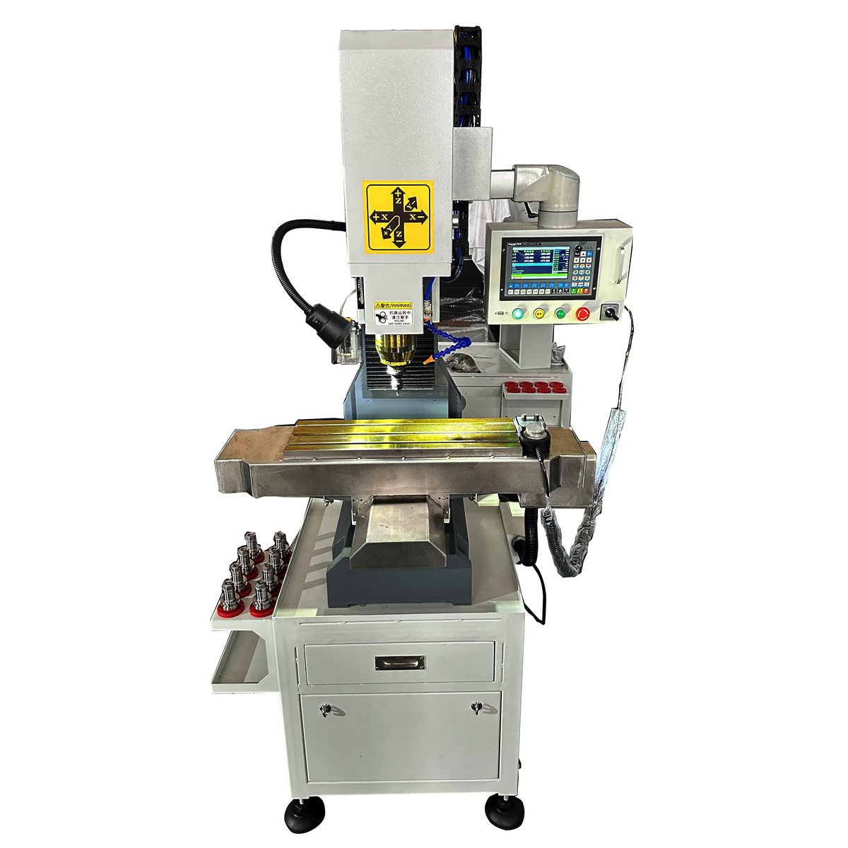 CNC Machining Center X/Y Axis Drifting (Z Axis Correct) – Step-by-Step Troubleshooting Guide
2026-08-22
Wizard for Solving CNC Machine Tool Displacement Drift Issues,step by step
Please contact us with your request
We are ready to answer your questions.